Mass Flow Controller
Compact Digital MFC / MFM MODEL EX-250S SERIES
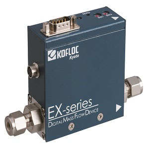
Compact Digital MFC / MFM MODEL EX-250S SERIES
EXCELLENT performance and compact mass flow device
Lower cost but high accuracy measurement.
High speed response and zero stability.
0-5VDC or 4-20mA input/output signal and +/-15VDC or 24VDC power supply.
Mediocrity D-sub 9pin.
Gases registered in EX-250S are usable by rotary-switch.
*Calculate the flow rate with conversion factor based on N2 gas.
RoHS compliance, CE marked.
Stand Specifications
|
Model
|
Mass Flow Controller
|
Mass Flow Meter
|
|
EX-250SC
|
EX-250SM
|
|
Sensor type
|
Thermal sensor
|
|
Valve type
|
Normally closed proportional solenoid valve
|
-
|
|
Applicable gases(*1)
|
N2、Air、H2、He、Ar、O2、CO2 etc.
|
|
(Gases not specifically mentioned here are subject to calibration for N2 equivalent.)
|
|
Flow range(*2)
|
10SCCM ~ 5SLM
|
|
Control(measure)range
|
2 ~ 100%(F.S.)
|
|
Response
|
≤ 1sec (within ± 2%F.S.)(*8)
|
|
Accuracy(*3)
|
± 1.0%F.S.
|
|
Repeatability
|
± 0.2%F.S.
|
|
Operating differential pressure(*4)
|
50 ~ 300kPa(Ar、CO2:100kPa ~ 300kPa)
|
-
|
|
Inlet maximum pressure
|
500kPa(G)
|
|
Proof pressure
|
980kPa(G)
|
|
External leak rate(He)
|
≤ 1.0 × 10⁻⁸Pa・m3/sec
|
|
Temperature
|
Working temp.
|
5 ~ 50℃
|
|
Accuracy guaranteed temp.
|
15 ~ 35℃
|
|
Allowable storage temp.
|
-10 ~ 60℃
|
|
Allowable operating humidity
|
10 ~ 90%RH (without dew condensation)
|
|
Materials of gas contact part
|
SUS316, SUS316L, magnetic stainless steel(*5), PTFE, FKM
|
|
Electrical connection
|
Dsub 9pin KFC Standard(SEMI standard compliant)
|
|
HR-10A
|
|
Flow rate setting signal
|
0~5VDC(input impedance: approx. 1M Ω)
|
-
|
|
or 4~20mA(input impedance: approx. 250 Ω)
|
|
Flow rate output signal
|
0 ~ 5VDC( load resistance ≧10k Ω)
|
|
or 4 ~ 20mA( load resistance ≧500 Ω)
|
|
Digital communication
|
RS485rotary-switch address setting
|
|
Required power supply (DC)
|
+15VDC( ± 5%)100mA , -15VDC(± 5%)150mA
|
|
or +24VDC(± 10%) ≤180mA (MFM would be ≤100mA)
|
|
Joint(*6)
|
1/4F900(standard)
|
|
Mounting posture
|
Horizontal installation recommended.
|
|
Weight(*7)
|
Approx.500g
|
Approx.440g
|
|
|
|
|
(*1) The gases must be dry and clean, free of corrosive components and foreign matter such as dust and mist.
|
|
(*2) The flow rate calibration units SCCM and SLM indicate a mass flow rate converted to a volume flow rate in cc/min
and L/min at 0°C and 1 atm.
|
|
(*3) Accuracy for calibration gas: N2, flow range (max. full scale).
|
|
(*4) The operating differential pressure may differ depending on specifications.
|
|
(*5) Mass flow meter does not contain magnetic stainless steel.
|
|
(*6) Contact us for any other joints.
|
|
(*7) Exclusive of weight of joint.
|
|
(*8) Pressure condition would be needed when you order.
|
All Metal Digital MFC / MFM MODEL EX-550 SERIES
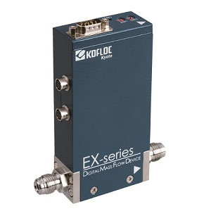
All Metal Digital MFC / MFM MODEL EX-550 SERIES
EXCELLENT performance and compact mass flow device
Metal sealing design
Lower cost but high accuracy measurement.
High speed response and zero stability.
0-5VDC or 4-20mA input/output signal and +/-15VDC or 24VDC power supply.
Mediocrity D-sub 9pin.
Gases registered in EX-550 are usable by rotary-switch.
*Calculate the flow rate with conversion factor based on N2 gas.
RoHS compliance, CE marked.
|
Model
|
Mass Flow Controller
|
Mass Flow Meter
|
|
EX-550C
|
EX-550M
|
|
Sensor type
|
Thermal sensor
|
|
Valve type
|
Normally closed proportional solenoid valve
|
-
|
|
Applicable gases(*1)
|
N2、Air、H2、He、Ar、O2、CO2 etc.
|
|
(Gases not specifically mentioned here are subject to calibration for N2 equivalent.)
|
|
Flow range(*2)
|
10SCCM ~ 5SLM
|
|
Control(measure)range
|
2 ~ 100%(F.S.)
|
|
Response
|
≤ 1sec (within ± 2%F.S.)(*4)
|
|
Accuracy
|
± 1.0%S.P. (25%F.S. ~ 100%F.S.) , ± 0.25%F.S. ( ~ 25%F.S.)
|
|
Repeatability
|
± 0.2%FS
|
|
Operating differential pressure(*3)
|
50 ~ 300kPa(Ar、CO2:100kPa ~ 300kPa)
|
-
|
|
Inlet maximum pressure
|
350kPa(G)
|
|
Proof pressure
|
980kPa(G)
|
|
External leak rate(He)
|
≤ 1.0 × 10⁻¹¹Pa・m3/sec
|
|
Temperature
|
Working temp.
|
5 ~ 50℃
|
|
Accuracy guaranteed temp.
|
15 ~ 35℃
|
|
Allowable storage temp.
|
-10 ~ 60℃
|
|
Allowable operating humidity
|
10 ~ 90%RH(without dew condensation)
|
|
Materials of gas contact part
|
SUS316L、PTFE、Ni-Co
|
|
Electrical connection
|
Dsub 9pin KFC Standard(SEMI standard compliant)
|
|
HR-10A × 2
|
|
Flow rate setting signal
|
0~5VDC(input impedance: approx. 1M Ω)
|
-
|
|
or 4~20mA(input impedance: approx. 250 Ω)
|
|
Flow rate output signal
|
0 ~ 5VDC( load resistance ≧10k Ω)
|
|
or 4 ~ 20mA( load resistance ≧500 Ω)
|
|
Digital communication
|
RS485rotary-switch address setting
|
|
Required power supply (DC)
|
+15VDC( ± 5%)100mA , -15VDC(± 5%)150mA
|
|
or +24VDC(± 10%) ≤180mA (MFM would be ≤100mA)
|
|
Joint
|
1/4VCR
|
|
Mounting posture
|
Free
|
|
Weight
|
Approx.800g
|
Approx.550g
|
|
|
|
|
|
(*1) The gases must be dry and clean, free of corrosive components and foreign matter such as dust and mist.
|
|
(*2) The flow rate calibration units SCCM and SLM indicate a mass flow
rate converted to a volume flow rate in cc/min and L/min at 0°C and 1 atm.
|
|
(*3) The operating differential pressure may differ depending on specifications.
|
|
(*4) Pressure condition would be needed when you order.
|
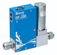
Digital Mass Flow Controller DF-200C SERIES
.jpg)
Digital Mass Flow Controller DF-200C SERIES
The DF-200 series is a high performance digital mass flow controller with ±1%S.P. accuracy and ≤1 sec response.
It also has multple-gas and multiple-range function of seven gases and the ease of changing the flow rate range of each gases.
・High accuracy(±1%RD),Fast response(1 sec.max.in all range)
・Multiple ranges and multiple gases supported
・Communications functions installed as standard feature(RS485)
・RoHS/CE Standard compliant
|
Sensor type
|
Thermal sensor
|
|
Valve type
|
Normally closed proportional solenoid valve
|
|
Applicable gases*1
|
Multiple gases : N2 (Air, H2, He, Ar, O2, CO2)*2
|
|
Flow range*3
|
10/30/50/100/300/500 SCCM, 1/3/5/10 SLM*2
|
|
Control range
|
2 to 100% (F.S.)
|
|
Response*4
|
Total flow rate control range ±1 sec (within ±2% F.S.)
|
|
Accuracy*5
|
±1.0% S.P. (> 35% F.S.)
±0.35% F.S. (≤ 35% F.S.)
|
|
Repeatability
|
±0.25% F.S.
|
|
Operating differential pressure*6
|
50 to 300 kPa (100 to 300 kPa for Ar and CO2)
|
|
Inlet maximum pressure
|
500kPa(G)
|
|
Proof pressure
|
980kPa(G)
|
|
External leak rate
|
≤1.0 x 10⁻⁸ Pa·m3/sec (He)
|
|
Temperature
|
Working temp.
|
5 to 50℃
|
|
Accuracy guaranteed temp.
|
15 to 35℃
|
|
Allowable storage temp.
|
-10 to 60℃
|
|
Allowable operating humidity
|
10 to 90% RH (without dew condensation)
|
|
Materials of gas contact part
|
SUS316, SUS316L, magnetic stainless steel, Ni, PTFE, PCTFE, and FKM
|
|
Electrical connection
|
D-sub 9-pin, KFC standard (SEMI standard compliant), RJ-45 modular jacks (two)
|
|
Flow rate setting signal
|
0 to 5 V DC (input impedance: approx. 1 MΩ)
|
|
Flow rate output signal
|
0 to 5 V DC (load resistance 10 kΩ)
|
|
Digital communication
|
Address setting with RS485 rotary switch : up to 99 devices (9600 bps)
|
|
Required power supply (DC)
|
+15 V DC (±5%): 150 mA, -15 V DC (±5%): 150 mA
|
|
Joint*7
|
1/4 F900 (standard), 1/4 UJR, Rc 1/4
|
|
Mounting posture
|
Horizontal installation recommended.
|
|
Weight*8
|
Approx. 850 g
|
|
*1 The gases must be dry and clean, free of corrosive components and foreign matter such as dust and mist.
|
|
*2 Dedicated software is available to change gases or change the actual full scale (F.S.) within the range of 30 to 100%
(30 to 80% for CO2 only) of the specified full scale.
|
|
*3 The flow rate calibration units SCCM and SLM indicate a mass flow rate
converted to a volume flow rate in cc/min and L/min at 0°C and 1 atm.
|
|
*4 Guarantee for calibration gas: N2.
|
|
*5 Accuracy for calibration gas: N2, flow range (max. full scale).
|
|
*6 The operating differential pressure may differ depending on specifications.
|
|
*7 Contact us for any other joints.
|
|
*8 Exclusive of weight of joint.
|
Digital Mass Flow Controller DF-250C SERIES
Digital Mass Flow Controller DF-250C SERIES
The DF-250 series is a high performance digital mass flow controller with ≤1 sec response less than 50SLM specification.
The series offers large flow rate line-up up to 300SLM.
・Standard gases are calibrated with actual gas
・~50SLM model offers fast response of ≤1 sec
・10sccm ~ 300SLM flow range line-up
・Communications functions installed as standard feature(RS485)
・RoHS/CE Standard compliant
|
Sensor type
|
Thermal sensor
|
|
Valve type
|
Normally closed proportional solenoid valve
|
|
Applicable gases*1
|
N2, Air, H2, He, Ar, O2, CO2, etc.
(Gases not specifically mentioned here are subject
to calibration for N2 equivalent.)
|
Air,N2
|
|
Flow range*2
|
10 SCCM to 10 SLM
|
20 to 50 SLM
(20 to 30 SLM for CO2)
|
100, 150 SLM
|
200, 300 SLM
|
|
Control range
|
2 to 100% (F.S.)
|
5 to 100% (F.S.)
|
|
Response*3
|
Total flow rate control range ≤ 1 sec (within ±2% F.S.)
|
≤ 1.5 sec / ≤ 3 sec less than 10%
(within ±2% F.S.)
|
≤ 2 sec (within ±2% F.S.)
|
|
Accuracy*4
|
±1.0% F.S.
|
±2.0% F.S
|
|
Repeatability
|
±0.25%F.S.
|
±0.5%F.S.
|
|
Operating differential
pressure*5
|
50 to 300 kPa
(100 to 300 kPa for Ar and CO2)
|
100 to 300 kPa
(150 to 300 kPa for Ar and CO2)
|
150 to 350 kPa
|
200 SLM : 200 to 350 kPa
300 SLM : 250 to 350 kPa
|
|
Inlet maximum pressure
|
500kPa(G)
|
|
Proof pressure
|
980kPa(G)
|
|
External leak rate
|
≤1.0 x 10⁻⁸ Pa·m3/sec (He)
|
≤1.0 x 10⁻⁷ Pa·m3/sec (He)
|
|
|
Working temp.
|
5 to 50℃
|
|
Temperature
|
Accuracy
guaranteed temp.
|
15 to 35℃
|
|
|
Allowable
storage temp.
|
-10 to 60℃
|
|
Allowable operating humidity
|
10 to 90% RH (without dew condensation)
|
|
Materials of gas contact part
|
SUS316, SUS316L, magnetic stainless steel, Ni, PTFE, PCTFE, and FKM
|
|
Electrical connection
|
D-sub 9-pin, KFC standard (SEMI standard compliant), RJ-45 modular jacks (two)
|
D-sub 9-pin ,
HR-10A (two)
|
|
Flow rate setting signal
|
0 to 5 V DC (input impedance: approx. 1 MΩ)
|
|
Flow rate output signal
|
0 to 5 V DC (load resistance 10 kΩ)
|
|
Digital communication
|
Address setting with RS485 rotary switch : up to 99 devices (9600 bps)
|
|
Required power supply (DC)
|
+15 V DC (±5%) : 150 mA
-15 V DC (±5%) : 150 mA
|
+15 V DC (±5%) : 150 mA
-15 V DC (±5%) : 250 mA
|
24 V DC (±10%) : 450 mA
|
|
Joint*6
|
1/4 F900 (standard), 1/4 UJR, Rc 1/4
|
1/2 SW (standard), 3/4 SW
|
|
Mounting posture
|
Horizontal installation recommended.
|
|
Weight*7
|
Approx. 850 g
|
Approx. 1000 g
|
Approx. 2250 g
|
Approx. 3500 g
|
|
*1 The gases must be dry and clean, free of corrosive components and foreign
matter such as dust and mist.
|
|
*2 The flow rate calibration units SCCM and SLM indicate a mass flow rate
converted to a volume flow rate in cc/min and L/min at 0°C and 1 atm.
|
|
*3 Guarantee for calibration gas: N2.
|
|
*4 Accuracy for calibration gas: N2, flow range (max. full scale).
|
|
*5 The operating differential pressure may differ depending on specifications.
|
|
*6 Contact us for any other joints.
|
|
*7 Exclusive of weight of joint.
|
Digital Mass Flow Controller with Indicator DF-300C SERIES
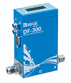
Digital Mass Flow Controller with Indicator DF-300C SERIES
The Model DF-300C Series is a mass flow controller with an integral
indicator that operates on a 24-V power supply, as developed
in response to the requests from users of the DF Series.
It inherits the features of the DF-200C Series with enhanced
convenience, including accuracy of ±1% S.P., response ≤1 sec (in
all ranges), and the multiple-gas, multiple-range versatility, i.e.,
support of seven gases (including reference gas) and the ease of
changing the flow rate range of each gas.
・High accuracy (±1% S.P.), fast response (≤ 1 sec in all ranges)
・Support of multiple ranges and multiple gases
・Communication functions installed as standard feature (RS485)
・RoHS CE standard compliant
・Driven by single 24 V DC supply voltage
・With or without indicator (selectable)
・Selectable Input/output signal
|
Sensor type
|
Thermal sensor
|
|
Valve type
|
Normally closed proportional solenoid valve
|
|
Applicable gases*1
|
N2 (Air, H2, He, Ar, O2, CO2)*2
|
|
Flow range*3
|
10/30/50/100/300/500 SCCM, 1/3/5/10 SLM*2
|
|
Control range
|
2 to 100% (F.S.)
|
|
Response*4
|
Total flow rate control range ±1 sec (within ±2% F.S.)
|
|
Accuracy*5
|
±1.0% S.P. (> 35% F.S.)
±0.35% F.S. (≤ 35% F.S.)
|
|
Repeatability
|
±0.25% F.S.
|
|
Operating differential pressure*6
|
50 to 300 kPa (100 to 300 kPa for Ar and CO2)
|
|
Inlet maximum pressure
|
500kPa(G)
|
|
Proof pressure
|
980kPa(G)
|
|
External leak rate
|
≤1.0 x 10⁻⁸ Pa·m3/sec (He)
|
|
Temperature
|
Working temp.
|
5 to 50℃
|
|
Accuracy guaranteed temp.
|
15 to 35℃
|
|
Allowable storage temp.
|
-10 to 60℃
|
|
Permissible ambient humidity
Allowable operating humidity
|
10 to 90% RH (without dew condensation)
|
|
Materials of gas contact part
|
SUS316, SUS316L, magnetic stainless steel, Ni, PTFE, PCTFE, and FKM
|
|
Electrical connection
|
D-sub 15-pin male, high density, HR-10A (two)
|
|
Flow rate setting signal
|
0 to 5 V DC (input impedance: approx. 1 MΩ), or 4 to 20 mA (input impedance: approx. 250 Ω)
|
|
Flow rate output signal
|
0 to 5 V DC (load resistance 10 kΩ), or 4 to 20 mA (load resistance ≤ 500 Ω)
|
|
Digital communication
|
Address setting with RS485 rotary switch or indicator: up to 99 devices (9600 bps)
|
|
Event input
|
Three contact inputs (non-insulated)
|
|
Event output
|
Three NPN open collectors (non-insulated, max. rating 35 V, 50 mA)
|
|
Required power supply (DC)
|
+24 V DC (±10%), 300 mA max. (DC jack, D-sub)
|
|
Joint*7
|
1/4 F900 (standard), 1/4 UJR, Rc 1/4
|
|
Mounting posture
|
Horizontal installation recommended.
|
|
Weight*8
|
Approx. 950 g
|
|
*1 The gases must be dry and clean, free of corrosive components and foreign
matter such as dust and mist.
|
|
*2 Dedicated software is available to change gases or change the actual full scale
|
|
(F.S.) within the range of 30 to 100% (30 to 80% for CO2 only) of the specified full scale.
|
|
*3 The flow rate calibration units SCCM and SLM indicate a mass flow rate
converted to a volume flow rate in cc/min and L/min at 0°C and 1 atm.
|
|
*4 Guarantee for calibration gas: N2.
|
|
*5 Accuracy for calibration gas: N2, flow range (max. full scale).
|
|
*6 The operating differential pressure may differ depending on specifications.
|
|
*7 Contact us for any other joints.
*8 Exclusive of weight of joint.
|
Mass Flow Controller/Mass Flow Meter with Indicator MODEL D8500 SERIES
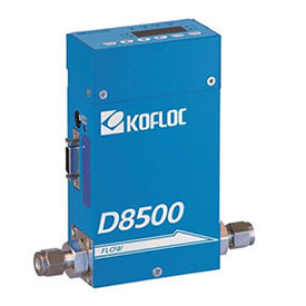
Mass Flow Controller/Mass Flow Meter with Indicator MODEL D8500 SERIES
This mass flow controller/meter driven by a 24 VDC power supply has been developed as a successor to the MODEL8300.
The view point change function of the display unit and the pattern setting function are unique to this model, and noise resistance has been improved dramatically. A sister model with a detachable display and setting unit is also available.
Features
・The high-lift actuator allows this compact model to control a large flow rate.
・Equipped with a display and setting unit, this model can be op-erated by a 24 VDC power supply.
・ The RS232C/RS485 communication function and integration function are provided as standard equipment.
・ The 14-bit converter permits display and operation in 4-1/2 dig-its.
・ Control of the flow rate of inflammable gas is possible, because the heat generating part of the sensor is not exposed to gas.
・ There are no limitations on the mounting position that may be employed.
・ In addition to SV setting, five other patterns can be set.
・ Auto zero and auto close functions are also standard.
|
|
|
Flow range (F.S.) (at N2 calibration conditions)
|
50 SCCM–5 SLM
|
Over 5 SLM–20 SLM
|
|
|
Applicable gases (dry gas)
|
N2, air, O2, CO2, Ar, H2, He, etc.
|
|
|
Sensor
|
Thermal mass flow sensor
|
|
|
Valve actuator
|
Normally-closed solenoid valve actuator *7
|
|
|
Valve type
|
Poppet valve *7
|
|
|
Control
system
|
Control/measurement range
|
2–100% F.S.
|
|
|
Response
|
0–100% F.S. or more within 2 sec. *1
0–below 10% F.S. within 4 sec. *1
|
|
|
|
|
Accuracy
|
Flow accuracy
|
±1.0%F.S. *2
|
±1.5%F.S. *2
|
|
|
Repeatability
|
±0.75%F.S.
|
|
|
Pressure
|
Proof pressure
|
1000 kPa (G)
|
|
|
Allowable operating pressure
|
500 kPa (G) or less
|
|
|
Operating differential pressure *7
|
50–300 kPa (G)
|
100–300 kPa (G)
|
|
|
Temperature
|
Allowable operating temperature
|
5–45℃
|
|
|
Temperature characteristics
|
0.2% F.S./℃
|
|
|
Humidity
|
Allowable operating humidity
|
10–90% (No condensation allowed)
|
|
|
Leak
|
He leak rate
|
1 × 10⁻⁸ Pa·m3/sec. or less *3
|
|
|
Flow setting
method
|
Digital
|
(1) Setting & display unit
|
|
|
(2) Communications
|
|
|
(3) Event input selection
|
|
|
Analog *7
|
(1) 0–5 V (2) 4–20 mA (freely selectable)
|
|
|
Flow rate output
|
Analog
|
(1) 0–5 V (2) 4–20 mA (interlocked with the above)
|
|
|
Display
|
Display format
|
7-segment 4-digit LED
|
|
|
Total flow
|
12 digits *4
|
|
|
Mounting direction
|
Changeable
|
|
|
Built-in/Separate
|
Built-in, separate 1 m, separate 3 m, separate 5 m
|
|
|
Status display LED
|
OK (within allowable range), ALM (alarm output interlock)
OUT1 (event output 1 interlock), OUT2 (event output 2 interlock)
SV (set flow), PV (instantaneous flow), TF (total flow)
IF (mode setting)
|
|
|
|
|
|
|
|
|
|
|
Other I/O
functions
|
Event input
|
3 × contact input
|
|
|
Alarm output
|
1 × open collector output, Max. 35 V, 50 mA
|
|
|
Event output
|
2 × open collector output Max. 35 V, 50 mA
|
|
|
Communications
|
RS-485, half-duplex, 9600 bps
|
|
|
Power supply
|
Rating
|
24 VDC, current consumption: 300 mA max.
|
|
|
Allowable supply voltage range
|
21.6–26.4 VDC (Ripple: 5% or less)
|
|
|
Mounting position
|
Not specified
|
|
|
Applicable standards
|
RoHS and EN62326-1: 2006
|
|
|
Materials of parts in contact with
gases
|
SUS316, SUS316L, SUS430, FKM, PTFE, chloroprene
rubber (option)
|
|
|
|
|
Joint
|
1/4 SWL, RC1/4, 1/4 VCR
|
|
|
Weight
|
Built-in: Approx. 1000 g
Separate (excluding the cable): Approx. 1200 g (*6)
|
|
|
|
|
|
|
(*1) Time required to reach the control flow ±2% F.S. from the fully closed state
|
|
(*2) With the standard pressure of 200 kPa (G) and the standard temperature of 20℃
|
|
(*3) Permeation is not included. The leakage by prolonged permeation shall not
exceed 1 × 10⁻⁶ Pa・m3/sec.
|
|
(*4) The units of measurement vary with the full scale flow. E.g.: With 1 SLM, the flows can
be added up to 9999 9999 9.999 L.
|
|
(*5) For other joints, please contact us. (*6) The weight may slightly vary depending on
the joint. (*7) These apply to the D8500MC mass flow controller.
|
|
High-grade Mass Flow Controller MODEL 3200 SERIES
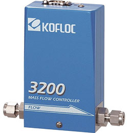
High-grade Mass Flow Controller MODEL 3200 SERIES
Model 3200 Series Mass Flow Controller is an advanced model designed as a successor of the 3910 Series that enjoys a wide use for diverse applications such as manu-facture of semiconductors, LCDs, combustion equipment, analytical devices, and biotechnology fields. Its high per-formance is equal to a new standard of KOFLOC.
・Equipped with a temperature follow-up type current difference detection flow sensor (patent applied for) to ensure high accu-racy and high-speed response
・Use of a normally closed valve to ensure safety
・Reduced dead volume thanks to the diaphragm seat valve
・Control of small quantities of flows available up to 1 SCCM fullscale (SR option)
・Low differential pressure type control available for combustiblegases (LP option)
|
Flow range (N2 equivalent,
20℃/1 atm)
|
1 SCCM–20 SLM (The conditions are freely selectable)
|
|
Sensor
|
Thermal mass flow sensor
|
|
Valve type
|
Proportional solenoid valve (closed when not energized)
|
|
Control range
|
2–100% (F.S.)
|
|
Response
|
1 sec. or less (0–100% within ±2% typical)
|
|
Accuracy
|
±1% F.S. (Accuracy guaranteed at 15–35℃)
|
|
Repeatability
|
±0.2%F.S.
|
|
Operating differential
pressure
|
F.S. ≤ 5 SLM: 50–300 kPa (G)
|
|
F.S.> 5 SLM: 100–300 kPa (G)
|
|
Option: Low differential pressure (LP) specification is available depending on conditions.
|
|
Allowable operating pressure
|
300 kPa (G) or less
|
|
Proof pressure
|
980 kPa (G)
|
|
Leak rate
|
1 × 10⁻⁸ Pa·m3/s or less (excluding permeation of He)
|
|
Allowable ambient
temperature
|
0–50℃
|
|
Allowable ambient humidity
|
10–90% (No condensation allowed)
|
|
Materials of parts in
contact with gases
|
Body: SUS316L
|
|
Diaphragm: SUS316
|
|
Valve seat: FKM (option: CR, NBR or perfluor)
|
|
Sealing: FKM (option: CR, NBR or perfluor)
|
|
Electric connection
|
Dsub 9-pin connector as per KFC Standard (Compliant with SEMI Standard)
|
|
Flow rate input signals
|
0–5 VDC (Input impedance: 1 MΩ or more)
|
|
Flow rate output signals
|
0–5 VDC (External load resistance: 250 kΩ or more)
|
|
Required power supply
|
+15 VDC (±5%) 100 mA, −15 VDC (±5%) 200 mA
|
|
Joint (Main unit bore)
|
Standard: 1/4SWL Option: 1/8SWL 1/4VCR RC1/4, etc.
|
|
Weight
|
Approx. 1000 g
|
!!Note !!
Specifications relating to the flow range (e.g., flow range, accuracy and re-sponse) are expressed in N2 or air equivalent. The product will be built with the primary pressure of 300 kPa or less and the secondary side open to the atmosphere. For details on the pressure requirements, please contact us.
Applications
Air sampling , Analyzer component , Bioreactor , Biotechnological process , Burn control
CCFL manufacturing , Chamber pressure control , Chemical process , Environment monitoring
Electronic device manufacturing , Food production , Fuel cell testing , Fermentation process
Gas blending , Gas distribution , Gas flow monitoring , Gas generation , Industrial furnace
Leak testing , Pharmaceutical process , Pollution monitoring , Process flow control
R&D, Solar power element manufacturing
Compact Handy Mass Flow Control/Measurement Unit FLOW COMPO
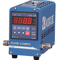
Compact Handy Mass Flow Control/Measurement Unit FLOW COMPO
This is a compact handy flow control/measuring unit made by combining a compact DIN72 x72 power indicator [CR-400] and MFC/MFM.
・ Compact, lightweight integral unit
・ The touch panel type permits easy FS scaling, flow setting, and valve opening/closing.
・ Free selection of joints ranging from one-touch type to Swage-lock.
・ The MFC-equipped type (FCC Series) can be used as MFM by pressing the OPEN switch.
・ Please contact us for the metal seal specifications for corrosive gas.
|
MODEL
|
FCC-3000-G1
|
FCC-3000-G2
|
FCM-3000-G1
|
FCM-3000-G2
|
|
|
Mounting MFC/MFM
|
3660 (MFC)
|
3200 (MFC)
|
3760 (MFM)
|
3100 (MFM)
|
|
|
Standard flow range
(at N2 calibration condition)
|
10SCCM-20SLM
|
1SCCM-20SLM
|
10SCCM-20SLM
|
1SCCM-20SLM
|
|
|
Sealing material
|
FKM (option CR or NBR)
|
|
|
Response
|
Within 2 sec. (F.S. ±2%)
|
Within 1 sec. (F.S. ±2%)
|
Within 2 sec.
|
Within 1 sec.
|
|
|
Joint
|
Various joints are applicable.
|
|
For details of the specifications, refer to the mounting MFC/MFM and CR-400.


